MIL-PRF-49080D
4.5.1.1
Input and Output. The output voltage shall meet the requirements of 3.7.3 over
the load current range of 0 to 25 amperes and over the input voltage range 100 to 126.5 volts/
207 to 253 volts, 60 Hz.
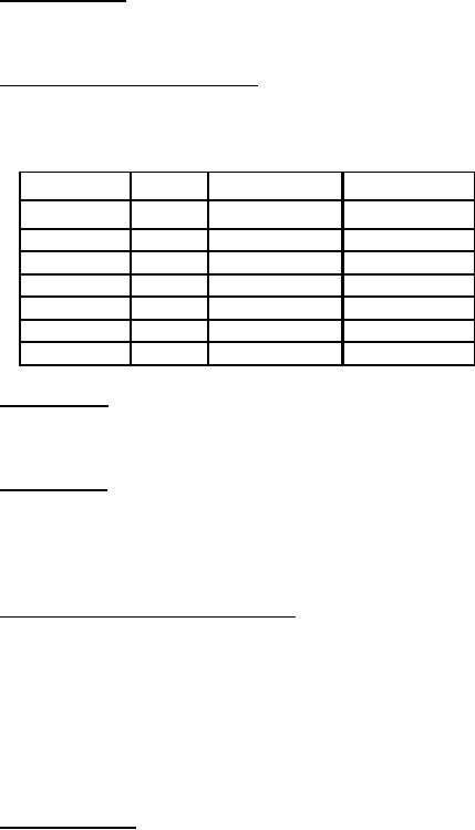
Frequency-voltage-load matrix test. The output voltage shall meet the
4.5.1.2
requirements of 3.7.3 when the load, input voltage (using appropriate input connector), and
frequency are varied as specified below; also when the external control is adjusted over the
output voltage range:
Input Voltage
Type
Frequency
Load (amps)
100
0 to 25
VAC
47.5, 63, 420
VAC
115
47.5, 63, 420
0 to 25
VAC
126.5
47.5, 63, 420
0 to 25
VAC
207
47.5, 63, 420
0 to 25
VAC
230
47.5, 63, 420
0 to 25
VAC
241.5
420
0 to 25
VAC
253
47.5, 63
0 to 25
Ripple voltage. The peak to peak ripple voltage shall be measured with suitable
4.5.2
equipment having a bandwidth of 20 Hz to 10 MHz . This test shall be made using the following
input voltages: 103.5 VAC- 60 Hz, 115 VAC- 60 Hz, and 126.5 VAC 60 Hz. (see 3.7.4).
4.5.3
Recovery time. With the power supply operating from 115 VAC 60 Hz, the load
shall be switched from 25 to 0 amperes and the power supply switched on and off at each of the
load conditions. The voltage transients shall be noted on suitable equipment. This procedure shall
be repeated when the load is switched from 0 to 25 amperes. The transient voltage shall meet the
requirements of 3.7.5.
4.5.4
Overload protection and current limiting. With the power supply operating at full
load (25 amps) the load shall be increased gradually to a short circuit condition and the output
current noted during the current limiting condition. Upon removal of the short, the power supply
shall automatically return to normal operating conditions. Repeat five (5) times. The power supply
temperature and during the temperature tests of 4.6.1. The input voltage during the tests shall be
115 V RMS, 60 Hz. Visual examination shall be made for any physical damage that might have
occurred due to the overload conditions. (see 3.7.6.2 and 3.7.6.3). At the end of the test, the power
4.5.5
Power changeover. Connect a 24V nominal DC source (battery or power supply)
to the DC input connector (see 3.3.4.1). Using a 115 V, 60 Hz single phase variable supply, reduce
the AC input voltage until the power supply automatically changes over to DC and note the AC
voltage at this point. Increase the AC input voltage until the power supply automatically changes
back to AC and note the value of AC input voltages at this point. Repeat this test using 115 VAC
400 Hz. This test shall be conducted with both a 2 amp and a 25 amp load for each input voltage
and frequency specified. Proper "light" indication shall be checked for conformance to
requirements of 3.7.2. Under the power changeover condition, indicated when the indicator light
on the front panel labeled "DC EMER" is on, a check shall be performed to determine the
continuity and consistency of polarity of the circuit connecting the "battery in" plug and the "power
out" plug.
18
For Parts Inquires submit RFQ to Parts Hangar, Inc.
© Copyright 2015 Integrated Publishing, Inc.
A Service Disabled Veteran Owned Small Business