MIL-DTL-24765A(NAVY)
4.6.3 Insulation resistance tests. Insulation resistance tests shall be conducted with the battery isolated from the
circuit.
4.6.4 Dielectric withstanding voltage tests. Dielectric withstanding voltage tests shall be conducted with the
battery isolated from the circuit. Any evidence of arcing, flashover, or punctured insulation shall be interpreted as a
failure of the test. Corona (visible, audible, or odorous) shall not be considered as a failure.
4.6.5 Enclosures. Acceptability of the enclosures shall be determined by performance of the dripproof test in
accordance with MIL-STD-108.
4.6.6 Input power perturbations. The test shall be performed as follows:
a. The UPS shall be operated at minimum, nominal, and maximum input voltages at no-load and rated-load.
The input voltage of the UPS shall be raised and then lowered beyond the specified operation range for 3 seconds
and 50 milliseconds (ms), respectively. The UPS operation shall be as specified herein.
b. The UPS shall be operated at minimum, nominal, and maximum input voltages to supply rated-load. The
input power shall be interrupted for a period of 30 seconds and then restored to the original condition. The test shall
be repeated by interrupting the input power for periods of 100 and 50 ms. The UPS operation shall be as specified
herein.
4.6.7 Input voltage spikes. The UPS shall be operated at nominal input voltage to supply rated-load and an
applicable transient voltage as specified in 3.2.1.2 shall be applied between line-to-line and between line-to-cabinet.
The UPS operation shall be as specified herein.
4.6.8 Input current harmonics. The UPS shall be operated at nominal input voltage and frequency. The input
current harmonics of each input line shall be determined at no-load, 50 percent load, and rated load. The UPS
operation shall be as specified herein.
4.6.9 Input current balance. Rated input voltage shall be applied to the UPS balanced to ±0.5 percent of
nominal voltage. The UPS shall be loaded to 15, 50, and 100 percent of rated load balance to ±0.5 percent of
average. The UPS operation shall be as specified herein.
4.6.10 Starting time. The UPS starting time shall be determined with nominal input voltage under no-load and
full-load conditions. The test shall be repeated with the input voltage absent. The UPS operation shall be as
specified herein.
4.6.11 Grounding. The UPS shall be tested for grounding in accordance with MIL-STD-1399-300.
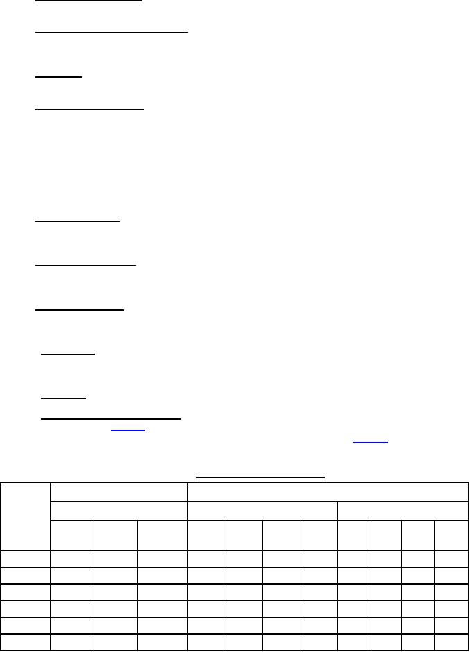
4.6.12 Voltage and frequency regulation. The UPS shall be connected to an input whose voltage and frequency
can be varied as specified in table IV. After the UPS has been stabilized at load, the output steady-state voltage and
frequency regulation shall be determined for each of the test conditions (TC) shown in table IV.
TABLE IV. Conditions of input and output.
Input
Output
Voltage & frequency
Rated load (percent)
Power factor
TC#
lag
lag
lead
Max.
Nom.
Min.
0
50
100
125
1.0
0.9
0.7
0.8
1
X
-
-
X
-
-
-
-
-
-
-
2-3
X
-
-
-
-
X
X
X
-
-
-
4
-
X
-
X
-
-
-
-
-
-
-
5-7
-
X
-
-
X
X
X
X
-
-
-
8-10
-
-
X
-
X
X
X
-
-
X
-
11
-
X
-
-
-
X
-
-
-
-
X
11
For Parts Inquires submit RFQ to Parts Hangar, Inc.
© Copyright 2015 Integrated Publishing, Inc.
A Service Disabled Veteran Owned Small Business